The conceptual foundation of a simple current-divider circuit lies in its ability to manage the distribution of electrical current across parallel resistive components. Such a circuit serves as a real-world application of the voltage division principle, which is as significant in electrical engineering as it is in practical electronic device implementations. By controlling the flow of current, a current-divider circuit maintains the function and safety of each component it serves.
The Principles Behind the Current Divider
Properly comprehending the current divider requires a grasp of Ohm’s Law, asserting that current flowing through a conductor is directly proportional to the voltage across it and inversely proportional to the resistance. This law is pivotal when examining current divider formula parallel circuit layouts, as it helps predict current distribution across the compartments of a circuit.
Ohm’s Law and its Application
Application of Ohm’s Law in the realm of a current-divider circuit is fundamental to determining the current share—one attributed to each path defined by resistances. It’s the backbone that guides us through the meticulous designs requiring precise current in distinct sections of an electronic circuit, embodying the voltage divider parallel resistors behavior.
The Role of Resistors in a Current Divider
In a current-divider circuit, resistors are critical for shaping its operation. The general voltage divider formula indicates that the electrical resistance provided by the resistors is central to regulating current flow, maintaining safety, and ensuring compatibility with each component’s specifications within the circuit. The formula implicates that more substantial resistance correlates with lesser current flow on that path.
Constructing a Basic Current-Divider Circuit
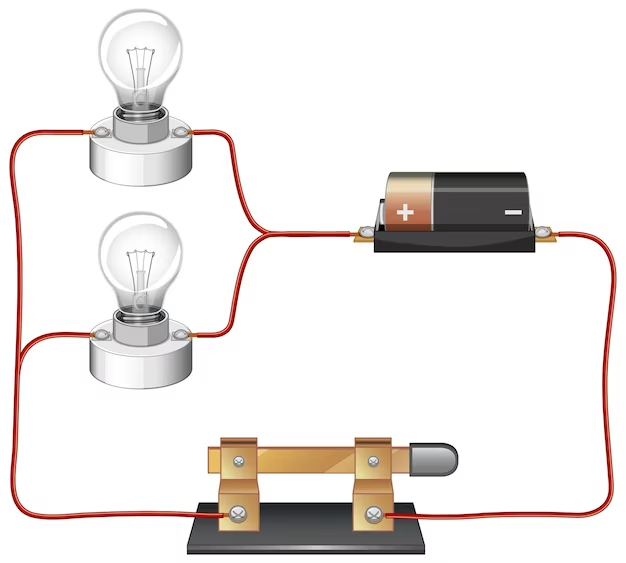
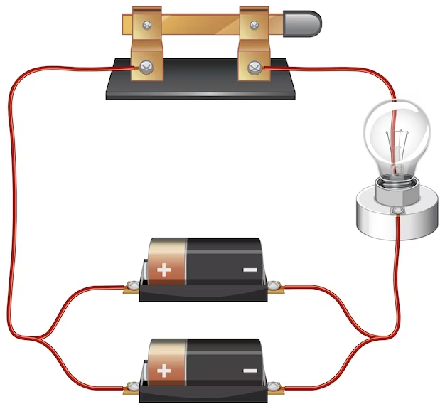
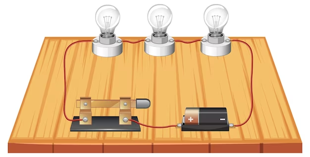
To assemble a simple current-divider circuit, one must gather the necessary components, such as a power source and parallel-connected resistors, and then follow an ordered assembly process. This basic setup exemplifies the implementation of a current divider formula parallel circuit in practice.
Components Required
- A constant power source (Voltage supply or battery)
- A pair or more of resistors, each with predefined resistance values
These components’ specifications are tailored to the circuit’s intended usage and performance expectations.
Step-by-Step Assembly Guide
- Begin by securing a voltage source appropriate for the voltage requirements of your circuit.
- Choose resistors with precise resistance values that are suitable for the power characteristics of the circuit.
- Connect the resistors in parallel configuration, ensuring a common junction at one termination, and similarly, another common connection point shared at the opposite termination. Lastly, establish a connection of these points with the power source’s positive and negative terminals.
How to Calculate Current Division
The division of current among parallel resistive paths is centered on a specific formula deriving from Ohm’s Law. Mastery of this formula is integral for efficient and accurate current-divider circuit design.
Understanding the Current Divider Formula
The current divider formula enacts a straightforward method to ascertain the current flowing through any resistor in a parallel arrangement.
Current Divider Rule: Ix = (Itotal) * (Rtotal / Rx)
Where:
- Ix denotes the current through the resistor Rx of interest
- Itotal represents the entire current entering the circuit
- Rtotal is the total resistance observed in the parallel circuit
- Rx is the individual resistance of the subject resistor
This rule allows for a simplified representation, especially when dealing with a two-resistor scenario within a parallel circuit. Such simplicity is what makes the general voltage divider formula so widely useful.
| Resistor | Formula for Current |
|---|---|
| I1 | Itotal * (R2 / (R1 + R2)) |
| I2 | Itotal * (R1 / (R1 + R2)) |
Practical Applications of Current Dividers
Current dividers are more than just theoretical constructs; they find extensive practical applications across various fields. From the simple gadgets we use daily to complex industrial systems, the concept of current division is critical for the proper functioning of electrical circuits.
Use in Electronic Devices
In electronic devices, from smartphones to computers, current dividers play an instrumental role. They ensure that sensitive components receive the correct amount of current and are protected from overcurrent conditions. An LED, for instance, might require lesser current compared to other components in a circuit, and a current divider is employed to allocate the necessary current for safe operation.
Industrial Applications
In an industrial setting, current dividers are integrated into the design of circuitry that controls machinery and industrial processes. These could range from regulating sensors to calibrating the operating current for motors. The reliability of such systems hinges on the precise division of current, ensuring that all components function optimally.
Troubleshooting Common Issues
Identifying and resolving issues in a current divider circuit is integral to maintenance and repair. It involves understanding possible complications and applying strategic measures to correct them.
Identifying Problems in a Current Divider Circuit
Common problems in a current-divider circuit may include inaccurately calculated resistor values, faulty connections, or damaged components. Diagnosing these issues requires a methodical approach, beginning with a review of the calculated vs. measured currents and inspecting for any signs of wear or damage.
Tips for Efficient Circuit Maintenance
- Regularly check and ensure all connections are secure and free from corrosion.
- Use precise measuring tools like a multimeter to verify the currents across the circuit match the expected values derived from the general voltage divider formula.
Conclusion
A simple current-divider circuit represents a fundamental concept that is invaluable to anyone involved in electrical engineering and electronics. Understanding the inherent principles, such as Ohm’s Law and the voltage division principle, constructing a basic circuit, calculating current distribution, and recognizing its practical applications, provides a solid foundation for creating, analyzing, and troubleshooting a myriad of electronic devices and systems.
FAQs
1. What is the primary purpose of a current-divider circuit?
The primary purpose of a current-divider circuit is to split the total input current into smaller currents that are proportionally divided among the resistive paths in a parallel circuit, according to their respective resistances.
2. Can we use the current divider rule for more than two resistors?
Yes, the current divider rule can be applied to any number of resistors in a parallel circuit, as long as the total current and individual resistances are known.
3. How does the current divider rule differ from the voltage divider rule?
The current divider rule is used to calculate the distribution of current across parallel paths in a circuit, whereas the voltage divider rule is used to determine the potential differences across components in series.
4. Why is it important to know the values of all resistors in a current-divider circuit?
Knowing the values of all resistors is essential because the distribution of current across the parallel branches is directly dependent on these values. Incorrect or unknown resistances would lead to incorrect calculations and potentially damage the circuit.
5. What are some common signs of issues in a current-divider circuit?
Common signs of issues include unexpected currents at various points in the circuit, overheating of components, fluctuating power supply readings, or even complete failure of an electronic component. These can signal an error in resistor values, poor connections, or failing parts within the circuit.